R&L Electronics
Text Questions to
513-868-6399
800-221-7735

   Catalog » Misc » MISC ANYTHING THAT DOES NOT FIT » CHAEMCOMMII My Account | Cart Contents | Checkout   


Search
 
Use keywords to find the product you are looking for.
Advanced Search
Icom
Jetstream
Kenwood
MFJ
Yaesu

Used Equipment

Links

Screen Savers
Brand
Email
Email
Subscribe to our email list
Unsubscribe to our email list
Catalog
Request Catalog
Download eCatalog
Store Info
FAQ
Map to Store
Special Events
Store Hours

CHAMELEON CHAEMCOMMII
[CHAEMCOMMII]

$149.95

EMERGENCY HF ANTENNA 6M-160M 500W SSB/250W CW

We had 1 of this item in stock at the time of the last update.


The CHA EMCOMM II Antenna has been specially designed for backup emergency HF system or permanent installation. The integral broadband impedance matching network (transformer 5:1) allows broadband antenna tuning.

It is the perfect backup antenna for apartments, condominiums, homeowners associations, deed restrictions and CCRs (Covenants, Conditions & Restrictions), ARES, RACES, MARS, EMCOMM, NVIS, First Responders and especially for Emergency
Preparedness.

The unit is totally waterproof. The antenna is 60' long and covers 6M to 160M. An external tuner might be required.

The antenna will perform very well with a sloper or an inverted "L" configuration. For a NVIS configuration (40M - 80M) the antenna must be installed horizontally with the ground and elevated between 9' and 12' high.

The CHA EMCOMM II do not required any ground-plane but will perform better with one. A ground terminal is available for that purpose.


Specifications:

Frequency: 6M - 160M

Power: 500W SSB or 250W CW

Length: 60' Copper Clad KEVLAR PTFE (Teflon) (-70øC to 150øC) wire

Weight: 2.0 Lb.


The antenna system consists of:

1 X CHA EMCOMM II matching box

1 X 60' Copper Clad KEVLAR Wire


Sloper Installation

The sloper is considered the most unusual antenna system and can be difficult to get to work properly. The sloper may exhibit some gain in one direction, but usually has omni direction pattern. There are two types of sloper, the full
sloper, really a dipole mounted with one end higher than the other. The half-sloper (EMCOMM II) is fed at one end with a "ground system" or counter poise provided by either physical ground if fed at lower end of sloper. If the sloper is fed
at the top, then other factors provide the "ground". In most cases, a sloper mounted on a tower, then the tower and importantly, the beam mounted on top, act as the counterpoise.

One successful version of the sloper (most folks call any kind of sloper simply a "sloper" regardless of its type) is one that is fed with coax. The antenna is fed from the top and installed on a tower with a beam on top. The center
conductor of the coax feeds the sloper wire and the shield is carefully bonded to the tower structure. In addition the beam, rotor, and mast are electrically bonded to the tower (here a heavy braided strap connecting the mast to the tower
is recommended). The theory is that the sloper is fed at the top and the high current point is high just under the beam, leading away from the tower.

The sloper has been reported to be hard to get to work in some cases. When it works, its performance when used with a tower and a beam is very good. Considering the cost of materials (assuming the tower is in place already) the sloper
should be considered.


Inverted "L" Installation

This is most likely the least expensive high performance antenna you can erect for 40M, 80M and 160M (limited performance). It is worth investigating since it needs only one high point in the relative clear to be effective (the horizontal
far end can be at a lesser elevation, details later). Most likely you will need to use an external antenna tuner.

The main radiating component of the "L" is the vertical wire, that's what makes it a very good ground-wave and DX antenna. So it would be good if this can be kept in the clear, or several feet away from your tower, and of course, as high as
you can make it. The horizontal part may slope downward, or bent several times to accommodate any obstacles. Keep in mind, the more you bend the element back on itself, the more of the radiated signal is canceled out.

Sometimes it is not possible to have the vertical section longer than the horizontal section. This will result in more of the signal being radiated skyward to which NVIS (Near Vertical Incident Skywave) will occur. NVIS is a propagation
method that provides usable signals in the range between ground wave and skywave distances (usually 30 to 400 miles).

Before we go any further, this antenna requires a robust ground system. If your ground is poor, the antenna efficiency will be poor, and you will be troubled with RF in the shack.

The radiation pattern is omni directional, with a possible minor lobe in the direction of the horizontal portion.

Optional Accessories

CHAMELEON CHA130EMCOMM130' WIRE FOR EMCOMMII $ 109.95Buy CHA130EMCOMM
CHAMELEON CHA60EMCOMMI60' WIRE FOR EMCOMMII $ 63.95Buy CHA60EMCOMMI
EMERGENCY HF ANTENNA 6M-160M 500W SSB/250W CW MISC ANYTHING THAT DOES NOT FIT IN ANY CATEGORY MISC


Shopping Cart more
0 items
Manufacturer Info
Other products


Follow us on Facebook


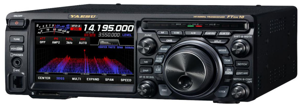
YAESU
FTDX10

HF TRANSCEIVER
$1379.95
Until 06/30/24


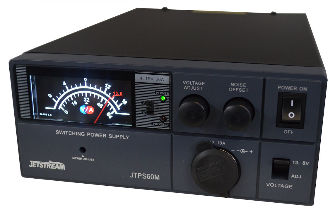
JETSTREAM
JTPS60M

60 amp power supply
$229.95


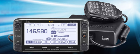
ICOM
ICID5100ADELUXE

Dstar Mobile
$0

Amplifiers and Preamps
HF Amplifiers
2m Amps/Preamps
Antennas
Multiband HF Base
Multiband HF Mobile
Multiband HF Portable
2m Base
2m Mobile
Multiband VHF/UHF Base
Multiband VHF/UHF Mobile
Multiband HF/VHF/UHF Mobile
Antenna Accessories
Duplexers
Triplexers
Rotators
Antenna Mounts
Magnet Mounts
Lip Type Mounts
Antenna Tuners
HF Automatic
HF Manual
Books
Study Guides

Cable, Coax, Wire
HT Jumpers
Ground Wire
Ladderline
Mini 8/RG8X w/Connectors
RG8 w/Connectors
Rotator Cable
Connectors
Adapters
Connector End
Power Supplies
Switching 15-40 amps
Transformer 15-40 Amps
Wall Cubes
Radios
2m Handhelds
2m/70cm Handhelds
2m Mobile
2m/70cm Mobile
HF Base
HF/VHF Base
Multiband HF/VHF Mobile
Radio Accessories
Clocks
Coax Switches
External Speakers
Lightning Arrestors
SWR Analyzers
TNC/Sound Card Interfaces
Wattmeters
Tower
Rohn 25G type
Rohn 45G Type

Copyright © 2024 R&L Electronics
1315 Maple Ave
Hamilton, Ohio 45011
800-221-7735
513-868-6574 Fax
sales@randl.com